


In the process of industrial production and manufacturing, some of the tanks measured are easy to crystallize, highly viscous, extremely corrosive, and easy to solidify. Single and double flange differential pressure transmitters are often used in these occasions. , Such as: tanks, towers, kettles, and tanks in coking plants; liquid storage tanks for the production of evaporator units, liquid level storage tanks for desulfurization and denitrification plants. Both single and double flange brothers have many applications, but they are different from the difference between open and sealed. Single-flange open tanks can be closed tanks, while double flanges have more closed tanks for users.
The principle of single flange pressure transmitter measuring liquid level
The single-flange pressure transmitter performs level conversion by measuring the density of the open tank,Level measurement of open containers
When measuring the liquid level of an open container, the transmitter is installed near the bottom of the container to measure the pressure corresponding to the height of the liquid level above it. As shown in Figure 1-1.
The pressure of the liquid level of the container is connected to the high pressure side of the transmitter, and the low pressure side is open to the atmosphere.
If the lowest liquid level of the measured liquid level change range is above the installation place of the transmitter, the transmitter must perform positive migration.
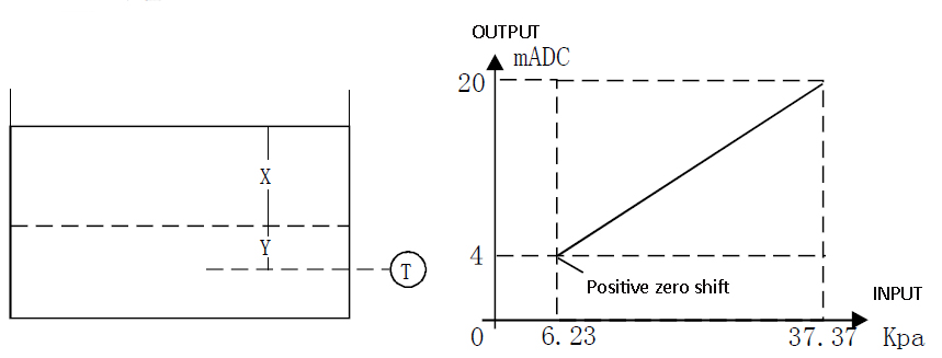
Figure 1-1 Example of measuring liquid in open container
Let X be the vertical distance between the lowest and highest liquid level to be measured, X=3175mm.
Y is the vertical distance from the pressure port of the transmitter to the lowest liquid level, y=635mm. ρ is the density of the liquid, ρ=1.
h is the maximum pressure head produced by the liquid column X, in KPa.
e is the pressure head produced by the liquid column Y, in KPa.
1mH2O=9.80665Pa (the same below)
The measuring range is from e to e+h so: h=X·ρ=3175×1=3175mmH2O=31.14KPa
e=y·ρ=635×1= 635mmH2O= 6.23KPa
That is, the measuring range of the transmitter is 6.23KPa~37.37KPa
In short, we actually measure the height of the liquid level:
Liquid level height H=(P1-P0)/(ρ*g)+D/(ρ*g);
Note: P0 is the current atmospheric pressure;
P1 is the pressure value of measuring the high pressure side;
D is the amount of zero migration.
The principle of double flange pressure transmitter measuring liquid level
The double-flange pressure transmitter performs level conversion by measuring the density of the sealed tank:Dry impulse connection
If the gas above the liquid surface does not condense, the connecting pipe on the low-pressure side of the transmitter remains dry. This situation is called a dry pilot connection. The method of determining the measuring range of the transmitter is the same as that of the liquid level in an open container. (See Figure 1-2).
If the gas on the liquid condenses, liquid will gradually accumulate in the pressure guiding tube on the low pressure side of the transmitter, which will cause measurement errors. In order to eliminate this error, pre-fill the low-pressure side pressure guiding tube of the transmitter with a certain liquid. This situation is called wet pressure guiding connection.
In the above situation, there is a pressure head on the low pressure side of the transmitter, so negative migration must be carried out (see Figure 1-2)
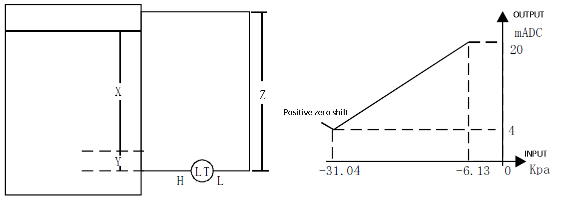
Figure 1-2 An example of liquid measurement in a closed container
Let X be the vertical distance between the lowest and highest liquid level to be measured, X=2450mm. Y is the vertical distance from the pressure port of the transmitter to the lowest liquid level, Y=635mm.
Z is the distance from the top of the liquid-filled pressure guiding tube to the base line of the transmitter, Z=3800mm,
ρ1 is the density of the liquid, ρ1=1.
ρ2 is the density of the filling liquid of the low-pressure side conduit, ρ1=1.
h is the maximum pressure head produced by the tested liquid column X, in KPa.
e is the maximum pressure head produced by the tested liquid column Y, in KPa.
s is the pressure head produced by the packed liquid column Z, in KPa.
The measurement range is from (e-s) to (h+e-s), then
h=X·ρ1=2540×1 =2540mmH2O =24.9KPa
e=Y·ρ1=635×1=635mmH2O =6.23KPa
s=Z·ρ2=3800×1=3800mmH2O=37.27KPa
So: e-s=6.23-37.27=-31.04KPa
h+e-s=24.91+6.23-37.27=-6.13KPa
Note: In short, we actually measure the height of the liquid level: liquid level height H=(P1-PX)/(ρ*g)+D/(ρ*g);
Note: PX is to measure the pressure value of the low pressure side;
P1 is the pressure value of measuring the high pressure side;
D is the amount of zero migration.
Installation Precautions
Single flange installation matters
1. When the single flange isolation membrane transmitter for open tanks is used for liquid level measurement of open liquid tanks, the L side of the low pressure side interface should be open to the atmosphere.
2. For the sealed liquid tank, the pressure guiding tube for guiding the pressure in the liquid tank should be piping on the L side of the low pressure side interface. It specifies the reference pressure of the tank. In addition, always unscrew the drain valve on the L side to drain the condensate in the L side chamber, otherwise it will cause errors in the measurement of the liquid level.
3. The transmitter can be connected to the flange installation on the high-pressure side as shown in Figure 1-3. The flange on the side of the tank is generally a movable flange, which is fixed at that time and can be welded with one click, which is convenient for on-site installation.
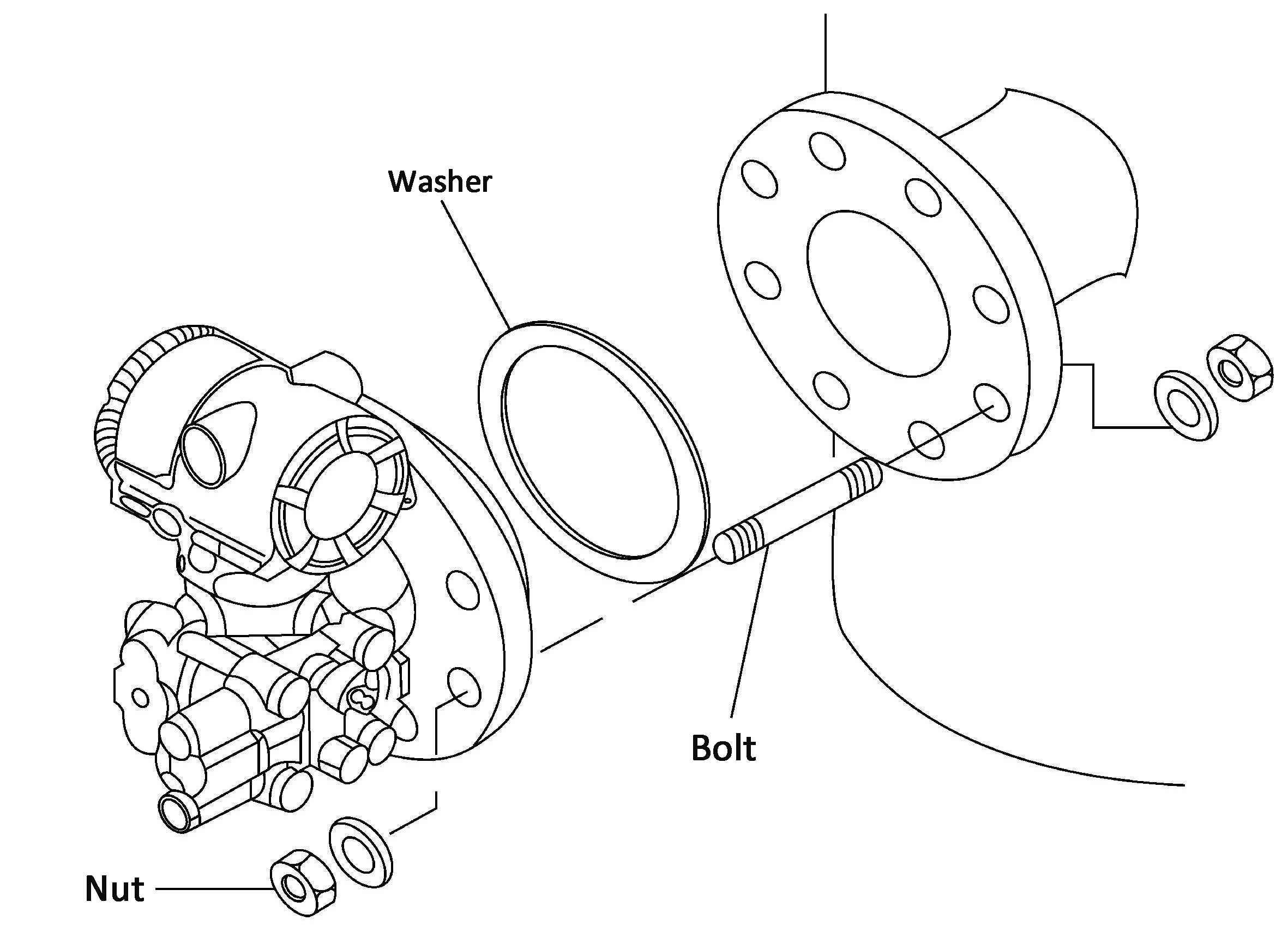
Figure 1-3 Installation example of flange type liquid level transmitter
1) When measuring the liquid level of the liquid tank, the lowest liquid level (zero point) should be set at a distance of 50mm or more from the center of the high-pressure side diaphragm seal. Figure 1-4:
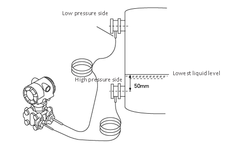
Figure 1-4 Installation example of liquid tank
2) Install the flange diaphragm on the high (H) and low (L) pressure side of the tank as shown on the transmitter and sensor label.
3) In order to reduce the influence of the environmental temperature difference, the capillary tubes on the high-pressure side can be tied together and fixed to prevent the influence of wind and vibration (the capillary tubes of the super long part should be rolled together and fixed).
4) During the installation operation, try not to apply the drop pressure of the sealing liquid to the diaphragm seal as much as possible.
5) The transmitter body should be installed at a distance of more than 600mm below the high-pressure side remote flange diaphragm seal installation part, so that the drop pressure of the capillary seal liquid is added to the transmitter body as much as possible.
6) Of course, if it cannot be installed 600mm or more below the installation part of the flange diaphragm seal part due to the limitation of installation conditions. Or when the transmitter body can only be installed above the flange seal installation part due to objective reasons, its installation position must meet the following calculation formula.
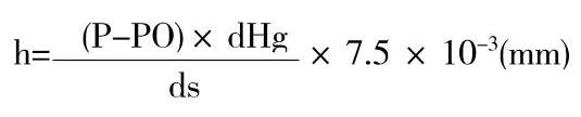
1) h: the height between the remote flange diaphragm seal installation part and the transmitter body (mm);
① When h≤0, the transmitter body should be installed above h (mm) below the flange diaphragm seal installation part.
②When h>0, the transmitter body should be installed below h (mm) above the flange diaphragm seal installation part.
2) P: Internal pressure of liquid tank (Pa abs);
3) P0: The lower limit of the pressure used by the transmitter body;
4) Ambient temperature: -10~50℃.
Post time: Dec-15-2021